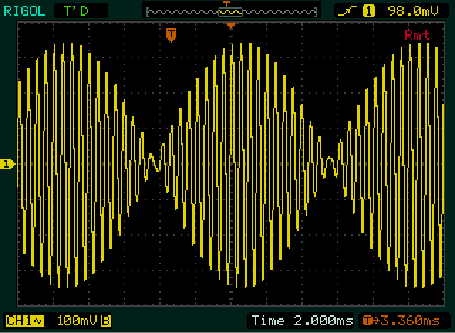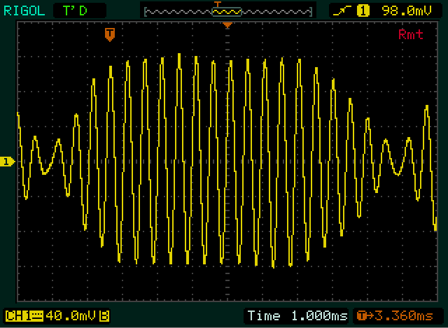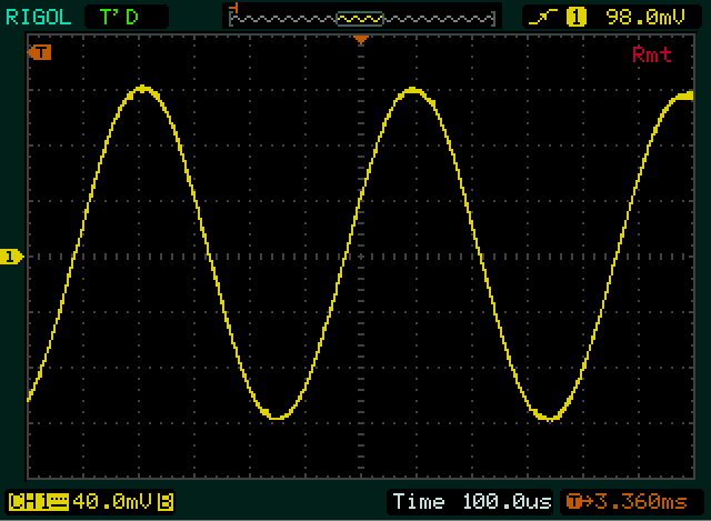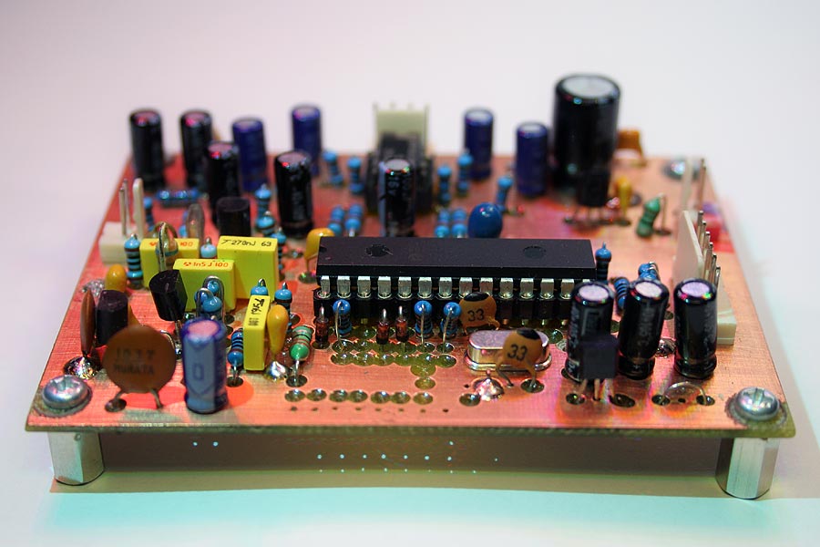
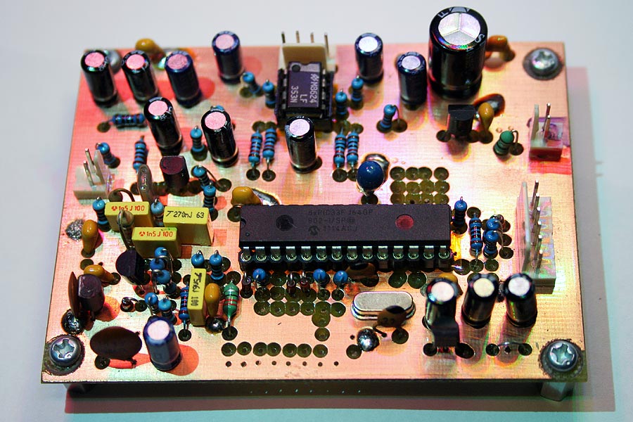
The circuit has undergone some changes since
these pictures were taken - This is the original v2.0 with an elliptic
input filter, a 40MHz crystal, and no 8 volt regulator or jumpers


Using the dsPIC33FJ64GP802
by Microchip
(for under $10AU)
40 MIPS @ 3.3V, 16k RAM,
64k FLASH, built-in stereo audio DAC with 256x oversampling, 1 x 10/12
bit ADC, 16 bit CPU design, and many other features
This processor is a real
DSP unit, and has many features to speed up processing such as:
Harvard architecture (separate
data and program busses)
Hardware support for multiply,
divide, MAC and data move instructions.
Two 40 bit DSP accumulators,
hardware multiplier, hardware divider (max 32/16 bit in only 18
CPU cycles), instruction prefetching, hardware saturation, hardware rounding,
barrel shifter, memory mapped IO, multiple DMA channels, multiple IRQs,
multiple clock sources, in-system low-voltage programming... the list goes
on!
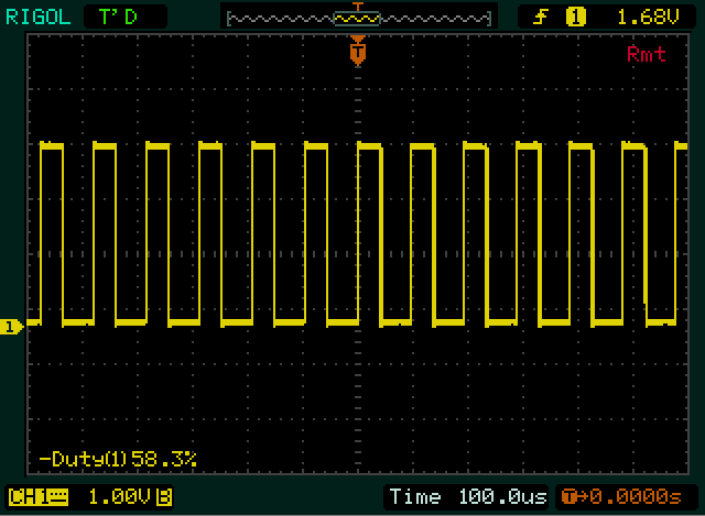
CPU Usage - An I/O pin
was cleared at the start of sample processing, and set when the CPU returned
to IDLE mode.
The resulting output
waveform shows the CPU usage.
The signal processing structure is as follows:
FIR Oversampling filters
The ADC runs at 16 times
the processing samplerate, to ease input filter requirements and increase
SNR.
DMA is used to collect 16
samples into RAM, and avoid CPU overhead.
Two FIR filters are used,
to reduce the sample rate by a factor of two, then eight.
This improves filter performance.
The FIR filter structure
uses the very efficient pipelining modes of the dsPIC and the repeat instruction
for fast, no overhead looping.
Chebychev highpass IIR
filter
Removes DC offset and subsonic
signals. Adds some phase rotation.
There are three of
these spread throughout the processing chain.
Uses error feedback to reduce
roundoff noise.
16-Stage IIR Phase Rotator
An allpass filter that spreads
the relative phase of the input audio to make voice waveforms more symmetrical.
Reduces peak levels, reduces
distortion and adds a characteristic sound.
EQ
A partial differentiator
produces a response that gently rises with frequency.
The EQ produces a flatter
voice spectrum, and makes the voice sound "sharper".
It uses only eight
instructions, including CPU saturation mode setting.
Look-ahead input compressor
Raises gain level slightly and limits signal maximums.
The look-ahead structure used in all the compressors
allows a slower attack time without signal clipping. This reduces distortion
and increases loudness.
The absolute value of the audio samples is integrated
to get a control signal. The control signal is converted to an inverse
function by dividing it into a large number.
A small RAM buffer delays the audio before the
samples are multiplied by the inverse, which brings the output to a constant
average level (above threshold).
This produces a compression ratio of infinity,
and the forward acting loop structure ensures unconditional stability.
Multiband look-ahead compressor
A multiband compressor is
important for maximizing the intelligibility of the signal, by enhancing
weaker voice components.
It also helps automatically
EQ the audio to a small degree, provides pre-emphasis and performs sibilance
limiting.
The current version uses
six
bands.
Per-band noise gate
Downward expands the compressor
output below a preset threshold, to reduce background noise.
The noise gate has now been
integrated into the multiband compressor, so it's bandpass filters prevent
any distortion products generated by noise gate control ripple.
Hilbert Transform Filter
The Hilbert Transform filter
adds a 90 degree phase shift to the entire audio spectrum.
This enables accurate measurement
of audio levels and avoids aliasing (due to the sampled nature of digital
audio).
Look-ahead output compressor
Makes up for variations
in level due to the multiband outputs adding in random phases.
Provides a more constant
drive level to the Hilbert Clipper.
Hilbert Transform clipper
Limits signal amplitude,
increases average power.
Produces intermod distortion,
but almost no harmonic distortion. This is visible looking at the scope
captures that show the audio envelope being clipped, but the waveform remaining
a sinewave.
This is very important when
feeding an SSB transmitter, as it avoids generating squared edges on the
audio waveform that can cause the SSB envelope to exhibit larger peaks.
Output filtering and transceiver
EQ
Cleans up some IMD from
the Hilbert Clipper, and provides bass boost to help compensate for transceiver
filtering.
Output gain compensation
This switches audio levels
to compensate for different filter gains, and different processing levels.
The version 2.0 speech processor using this board has these features:
