EasyDRF-MFSK
NOTE: The MFSK version has now been changed to CSK. The project has moved HERE
The original EasyDRF uses OFDM modulation. OFDM is fast and bandwidth efficient, but it has a high crest factor which reduces the average modulation power level through a transmitter.
In contrast, FSK modes use a single tone per baud, which has a lower crest factor. This raises the average power level of the modulated data signal by at least 6dB.
Because of this fact, an MFSK version of EasyDRF is being designed.
Orthogonality
Modems are normally designed to use orthogonal tones. This means the tone separation needs to be wide enough to keep the sidebands from the tone switching from crossing over to the next tone frequency. This is very important if the tones are simulataneous, like in OFDM. This is not so important in MFSK modes, as only one tone is sent at a time.
Orthogonal tones reduce the bandwidth efficiency of the modem, because they require more widely spaced tones - especially when the baud rate increases and the baud period gets shorter.
Using modern signal detection methods it may be possible to use non-orthogonal tones, which would allow more tones in the available bandwidth. This may improve modem performance, as it allows more bits to be sent per baud. However, early tests seem to indicate there is more SNR loss from closely spaced tones than there is from using shorter tones.
Closely spaced tones may cause problems with Doppler shift, as it will cause the tones to change frequency. Using chirp spread-spectrum methods may help prevent this.
Doppler spread is likely to be less of a problem with MFSK than OFDM, because the simultaneous OFDM tones are likely to cross over each other, causing more data loss - whereas the degradation MFSK might suffer can only be incorrect tone detection during the bauds.
Shortwave propagation problems
Signals propagated by shortwave are degraded by various problems:
- Delay spread - Multipath propagation causes the frequencies in the signal to arrive at variable times, spread over some mS.
- Doppler spread - Multipath propagation and geomagnetic storms cause the frequencies in the signal to vary. This can be as much as 50Hz in severe cases.
- Noise - Signal detection is limited by atmospheric and manmade noise levels.
Possible ways to improve data decoding:
- Use single-tone modulation to put all the power on one frequency for best SNR. This should improve received audio SNR by 6 to 10 dB over OFDM.
- Use spread-spectrum techniques to spread frequencies in the data signal to avoid multipath fading notches and reduce the effect of Doppler shift. The decoder despreads the signal before detection. This puts all the tone power back on one frequency again for best SNR.
- Use wider tone spacing to reduce the effect of Doppler shift.
- Rotate frequency usage to avoid interference.
- Detect energy increases in the signal each baud period.
- Equalize propagation delays in the received data signal.
Standard methods:
- Use interleaving to spread out decoding errors.
- Use CRC checking to validate data.
- Use error correction to correct decoding errors.
Modes
Some modes being evaluated are:
Spread-Spectrum modes
These modes use different spreading pattern codes (not FSK frequencies) to convey data symbols:- PN Code Shift Keying - This uses PN (Psudo-Noise) codes to chirp modulate (FM) a sinewave. At least 1024 codes are possible.
- Sine Code Shift Keying - Uses sinewaves to chirp modulate (FM) the sinewave tones. The modulation sinewaves are also chirped to make them more different to each other.
- Sawtooth or triangle Code Shift Keying - Uses sawtooth or triangle waveforms to chirp modulate (FM) the sinewave tones. The sawtooth or triangle waveforms are also stepped among different frequencies and phases to make them different to each other.
All of these Spread Spectrum modes may be phase sensitive, so they may require an adaptive equalizer to perform well on shortwave.
The decoder multiplies each incoming baud with each of the possible codes of an identically chirped FM sinewave in an IQ mixer. The output of the IQ mixer is integrated and the vectorsum is measured. The matching code causes a zero-beat, causing the integrator to deliver a DC signal, while the non-matching signals cause a mostly AC waveform that causes the integrator to stay closer to zero output.
Since there is no FM detector used, this method should perform very well, even with noisy signals and propagation phase errors.
MFSK modes (including chirped modes)
| Standard FSK | |||||||||
|---|---|---|---|---|---|---|---|---|---|
| Mode | Tones | Bits | Spacing | Baud | Tone BW | Raw speed | |||
| 257FSK | 257 | 8 | 15.625Hz | 4.0mS | 250Hz | 2000bps | |||
| 129FSK | 129 | 7 | 31.25Hz | 3.5mS | 285Hz | 2000bps | |||
| 65FSK | 65 | 6 | 62.5Hz | 3.0mS | 333Hz | 2000bps | |||
| 33FSK | 33 | 5 | 125Hz | 2.5mS | 400Hz | 2000bps | |||
| 17FSK | 17 | 4 | 250Hz | 2.0mS | 500Hz | 2000bps | |||
| 9FSK | 9 | 3 | 500Hz | 1.5mS | 667Hz | 2000bps | |||
| Chirped FSK | |||||||||
| Mode | Tones | Bits | Spacing | Baud | Tone BW | Raw speed | Sync | Frame | Chirp Hz |
| 256FSK | 256 | 8 | 15.625Hz | 4.0mS | 250Hz | 2000bps | 24b | 126sym | 2000 |
| 128FSK | 128 | 7 | 31.25Hz | 3.5mS | 285Hz | 2000bps | 21b | 144sym | 2000 |
| 64FSK | 64 | 6 | 62.5Hz | 3.0mS | 333Hz | 2000bps | 24b | 168sym | 2000 |
| 32FSK | 32 | 5 | 125Hz | 2.5mS | 400Hz | 2000bps | 20b | 200sym | 2000 |
| 16FSK | 16 | 4 | 250Hz | 2.0mS | 500Hz | 2000bps | 24b | 252sym | 2000 |
| 8FSK | 8 | 3 | 500Hz | 1.5mS | 667Hz | 2000bps | 24b | 336sym | 2000 |
Framing is LSB first.
Most of these modes are not orthogonal, which makes accurate tone detection more challenging. Using orthogonal modes may reduce the available speed of the modem, by reducing the number of tones (thus reducing the bits-per-baud), or it may reduce the tone SNR by requiring a higher baud rate. But the early tests seem to indicate the opposite is true.
All these modes are designed for AM shortwave broadcast, and use from just over 300Hz to about 4.5kHz of the audio passband. This allows a slight increase in data bandwidth.
The standard FSK modes have an extra symbol code to indicate a repeated symbol. This is required for standard FSK to allow constant baud sync. Chirped modes can keep good baud lock from the chirp waveform alone, and may have slightly better performance without the extra code, as one symbol error on a repeated symbol never causes two errors.
Not all these modes will be used, but various modes will be tested for practicality.
These modes have had tests done on-air:
* Plain 257FSK 4mS, 8 bits - 257 tone FSK. Tone spacing was 16Hz. Bandwidth was from about 320 to 4500Hz.
* Plain 65FSK 3mS, 6 bits - 65 tone FSK. Tone spacing was 64Hz. Bandwidth was from about 320 to 4544Hz.
The next round of tests was better, but still had too many errors due to multipath:
* 256FSK 4mS, 8 bits, chirped.
* 128FSK 3.5mS, 7 bits, chirped.
* 64FSK 3mS, 6 bits, chirped.
* 32FSK 2.5mS, 5 bits, chirped.
* 16FSK 2mS, 4 bits, chirped.
* 8FSK 1.5mS, 3 bits, chirped.
All these early tests had no ECC.
Any data modes used will require two layers of FEC. LDPC and RS layers are likely the best choices.
Spread Spectrum
Spread spectrum methods can improve the modem performance by evening out both the channel response and the modem response.
Spread Spectrum is a way of spreading a signal out across a particular bandwidth, and un-spreading it at the receiver/decoder. This "dilutes" the signal across the spreading bandwidth, which helps to even out the effects of narrowband interference and propagation disturbances in the channel. In this application, the spreading bandwidth is only within the communications channel.
The decoder despreads the signal, putting all the power back on one frequency. If the original frequency was a single-frequency audio tone, then the result will also be a single-frequency. If the despreading is done by zero-beat, then the output will be DC. The despreading of the signal also spreads the channel noise, causing a drop in the noise floor in the decoder.
With a constant-amplitude data modulation like MFSK, the most suitable Spread Spectrum mode to use would probably be chirp. Chirp typically uses a sawtooth ramp to sweep the signal over a range of frequencies, but other waveforms can also be used.
PN code chirp
Tests conducted with a PN (psudo-noise.. random numbers) based chirp spreading code showed that it was readily possible to encode and decode up to 1024 different symbol patterns on the same channel. However, it also showed that the signal became phase-sensitive, which is a troublesome side effect - as shortwave signals are often distorted in phase by multipath propagation.
- When a different PN coded despreading chirp is applied in the decoder, the decoded result resembles noise.
- When a matching PN coded despreading chirp is applied in the decoder, the decoded result has a high DC value, and very low noise. Phase errors from filtering or propagation increase this noise value, as they change the PN phase characteristics, causing degradation.
- It may be possible to adaptively tune a channel equalizer by observing the decoded noise level to compensate for this.
- The noise generated by using a different PN code in the decoder can be high amplitude. This AC noise needs to be reduced by an integrator to avoid false symbol detection.
Linear ramp chirp
A linear ramp chirp may be more suitable for this application. This is because a linear ramp has relatively low frequency content, so it will have less phase distortion problems from propagation. A linear ramp can still spread an audio tone across a range of frequencies to help avoid amplitude notches from multipath. After despreading, the tone will be back on the original frequency, where it can be sent to an FFT for tone (symbol) detection, or for CSK it can be zero-beat.
Linear ramp chirp can also improve the isolation between narrowly spaced tones, by using different ramp slopes for adjacent tones. This could improve the apparent tone spacing of the MFSK, which would be useful for reducing or eliminating the effects of Doppler spread.
Sinewave chirp
A sinewave chirp might be the easiest waveform to easily recover, as the chirp modulation waveform is only one frequency. This allows it to be filtered without changing the waveform shape. A combination of filtering and Hilbert clipping can effectively suppress noise on the recovered sinewave. The recovered sinewave could then be used for chirp and baud synchronization. Each baud rate has a different period, so each has a different chirp modulation frequency - therefore each will need it's own filter.
Sawtooth or Triangle chirp
A sawtooth or triangle chirp can also be used to encode the signal. A good pattern needs to be contructed by using different frequencies and phasing of each code. Ideally, each code should have very low correlation with all other codes for good results. This requires minimal overlap of the waveforms, although they can cross over each other. The advantage of these waveforms is that they will contain a lower frequency content than a PN code, and could possibly be mapped out to have higher isolation and thus better signal separation compared to PN codes that rely on statistical patterns to avoid each other.
Protocol
A protocol is required to transmit data in an orderly way. Transmitted symbols are grouped into frames for transmission. File objects are transmitted in segments. Each segment has a header, containing important decoding information such as segment number, segment size, transport ID, and CRC code.
The HamDRM/EasyDRF protocol uses two layers - an inner layer of frames with Convolutional coded ECC, and an outer layer of data segments with Reed-Solomon ECC. The data segments have CRC which is used to detect failed segments as erasures, to improve Reed-Solomon decoding performance by a factor of 2.
In the HamDRM/EasyDRF protocol, the filename data is sent in the header of segment 0. This is repeated at the end of the file data, in case segment 0 is lost. Since this does not guarantee the filename data will arrive, in EasyDRF the filename data is also sent in a header attached directly to the file. This guarantees delivery, but can't be decoded until there is adequate data present, due to the interleaved RS coding.
The current FSK modem design uses fixed frame sizes to avoid frame size errors due to a lack of error correction. When ECC is added later, this may change. Also there is currently no outer layer of ECC or data segments. This will be added later.
Fast Access
Ideally, a data modem should automatically sense the mode being used, and switch to it. This can be done by sending the mode at intervals, or by testing for each mode to find a match. In HamDRM and in EasyDRF this is done via the "Fast Access Channel".
Since each mode currently being evaluated in EasyDRF-MFSK has a constant bitrate, the baud rate increases as the FSK number gets lower. This means that each FSK type has a unique baud rate. Since the chirp rate is locked to the baud rate, this creates a unique chirp frequency for each mode. Measuring this chirp frequency allows automatic mode identification and switching. This is now fairly reliable and fast.
September 2024
The Chirped MFSK is proving difficult to decode correctly when affected by multipath. So far, a channel equalizer has not helped significantly, but the code may not yet be working correctly...
Instead, work is now focusing on Code Shift Keying.
Code shift keying uses a PN code, a sawtooth, triangle or sine waveform to FM a tone oscillator. This produces a flat envelope. The FM spectrum is carefully controlled by limiting and filtering.
If sawtooth, triangle or sine waves are used, they need to be randomized in different patterns to make a series of non-overlapping code waveforms. This requires some analysis to produce ideal spreading waveforms...
It appears very easy to encode and decode 1024 different symbols in a 4kHz channel using PN codes, but this needs to be tested on-air in real conditions to be proven.
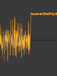
1024CSK PN code test - IQ mixer output:---- Earlier updates ----
Since the MFSK data modem requires a delay equalizer to counteract the effects of multipath propagation, code to do this has been tested.
A "Constant Modulus Equalizer" appears to be the most suitable for a constant-amplitude signal like MFSK.
A separate project for an advanced AM demodulator is being developed and it also requires some sort of adaptive equalization to cancel the effects of multipath, so the equalizer may be easier to test in this context.
---- Older updates ----
Modem design progress continues...
The first on-air tests with chirped FSK via an ionspheric path showed severe degradation.
* The chirp FM detector was severely degraded by multipath (this was expected to some degree).
* Baud timing relies on accurate chirp recovery, so timing was likely degraded also.
These issues need to be addressed at the modem level (not purely by adding ECC).
This will require an adaptive equalizer to reduce delay distortion, and probably an improved chirp FM detector.
Decoding lock at ~3dB SNR:
More sync pattern tweaks to improve decoding lock accuracy:

Frame sync has been improved further, by changing each symbol to use min or max values.
FSK tests (text files)
Without added noise
With -3dB peak added noise in a 5.5kHz bandwidth
Since there is no frame error correction, the frame sync detection has been configured to be tolerant of errors. The frame sync counts up to three good detections. This means there need to be four frame sync failures before the modem will retest the FSK mode. If the FSK mode is correctly detected, and it has not changed, the modem continues decoding normally. If the FSK mode is detected as different, the modem will be re-initialized in the new mode.
This means the frame sync can fail, and as long as the chirp + baud sync remains good, the modem will continue decoding and stay in sync, despite errors - as long as the FSK detection works correctly (it can fail in noisy conditions).
----The chirp sync display now has vertical stabilization:
Frame sync reliablility has been improved by making each sync code different enough to be unique. Ideally, the frames and frame sync need ECC to protect against errors.
Linear interpolation has been added to the timing sync code. This allows very accurate time alignment for the unchirp process, resulting in more stable FSK tones.
Frame sync needs improvement. Because the frame sync codes are too similar, they are sometimes mistaken for an incorrect mode, causing mode changes to reset many times in an attempt to find the correct mode. Ideally, frame sync coding should use an error-resistant protocol like RS coding...
----Automatic mode detection is now working. The baud rate is detected using a squaring detector, and the decoder is re-initialized in the new mode. This only takes a few seconds.
This is yet to be tested on a noisy, fading signal.
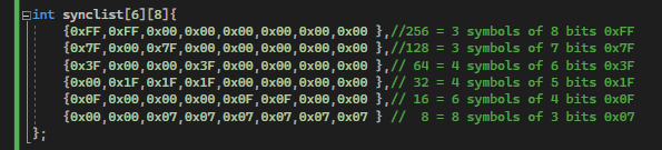
Chirped FSK modes from 8FSK to 256FSK are all enabled and working in EasyDRF-MFSK. Bit conversion from 8 bits down to the modem widths of 3 to 8 bits and back is working in all FSK modes. Timing sync is very good, but could perhaps be improved further. Frame sync is working well, but could also be improved by using better methods. Sync is currently indicated by a run of all 1's symbols. Sync width is 20 to 24 bits, depending on mode.
Since no error correction is currently available, it was decided to use a fixed frame size to eliminate frame header errors. This means that each mode has a frame size of 1008 bits (126 bytes) - except for 32FSK which uses 1000 bits (125 bytes).
When error correction is added, it must either work well directly with the bit width of the particular mode, or a robust sync method needs to be used to ensure the ECC coding doesn't lose bit sync.
----
Since chirped MFSK is likely to have the best performance, this mode is the main focus - as it is likely to better handle multipath, Doppler and interference effects.
For modem evaluation, there is no error correction at this time - although it will be essential for good performance.
The sinewave based chirp can be recovered from the signal with high reliability, for good sync.
Unchirping a signal removes the signals required to maintain chirp sync, so the decoder is using a parallel path where the chirp signal is analyzed at the input side. Currently, a standard FM detector is being used for this, but an idea for an FFT based chirp detector is in development.
The FSK tones are inwardly-chirped towards the channel centre to conserve bandwidth. This allows wider FSK tone spacing. This also flips the chirp phase on up and down chirps, allowing easy chirp detection. The phase flips are easy to decode, and the recovered sinewave can be flipped back to produce a continuous-phase sinewave for timing purposes.
The inward-chirp pattern causes the chirp to bias the FSK tones towards the channel centre. If the chirp is not completely removed from the FSK tones due to timing error, then there will be residual chirp and residual offset on the FSK tone frequencies. This may require another processing stage to remove the residual chirp error and the tone offset.
An FFT tone decoder follows the unchirp stage. Decoding tones using FFT is far better for noise rejection than an FM detector, due to the narrow FFT bands.
Modes with longer tones may provide better SNR on the tone detection, but as the tone spacing gets closer the tones become more difficult to separate due to their sideband overlap.
There is likely a sweet spot in the FSK types where these effects are both at reasonable values. After recent sync improvements, the performance in white noise appears to improve as the FSK number gets lower.
Actual decoded 65FSK via the UK on 15770kHz, without error correction or chirp (Transmitted text: "HELLO LISTENERS!"):
HELLO#LITYFNFSS$ HEMMN$MJTSGNVSU$ HEM`N$LITSFMGRJ$ HFLLO#LIST0NESR# HFMMO#LIRTFNFRT$1GFMMO#KIRSDNGRT$ G=LLOTLIRUFNFR[$ HFM`O#LHSSFNFRR$1HEMMO#MJRTENERS# GFMMP#LIRTEOEQR$ HELLP#&JRMEOERS# EO_O#MHRTXOERS$XHEMMP#MIRTFOEZR$ HEMMP""JQTEOEQS#ZHFN`P#NIRTEOFQS#3XT`[[N"LIST8OGQT\ HFMXP'!HRZZNWRI< HFM`P&LIIS\NDSE%!GEM`N$LI[TXNFQS%!HFLLN'LITTFMZRU$
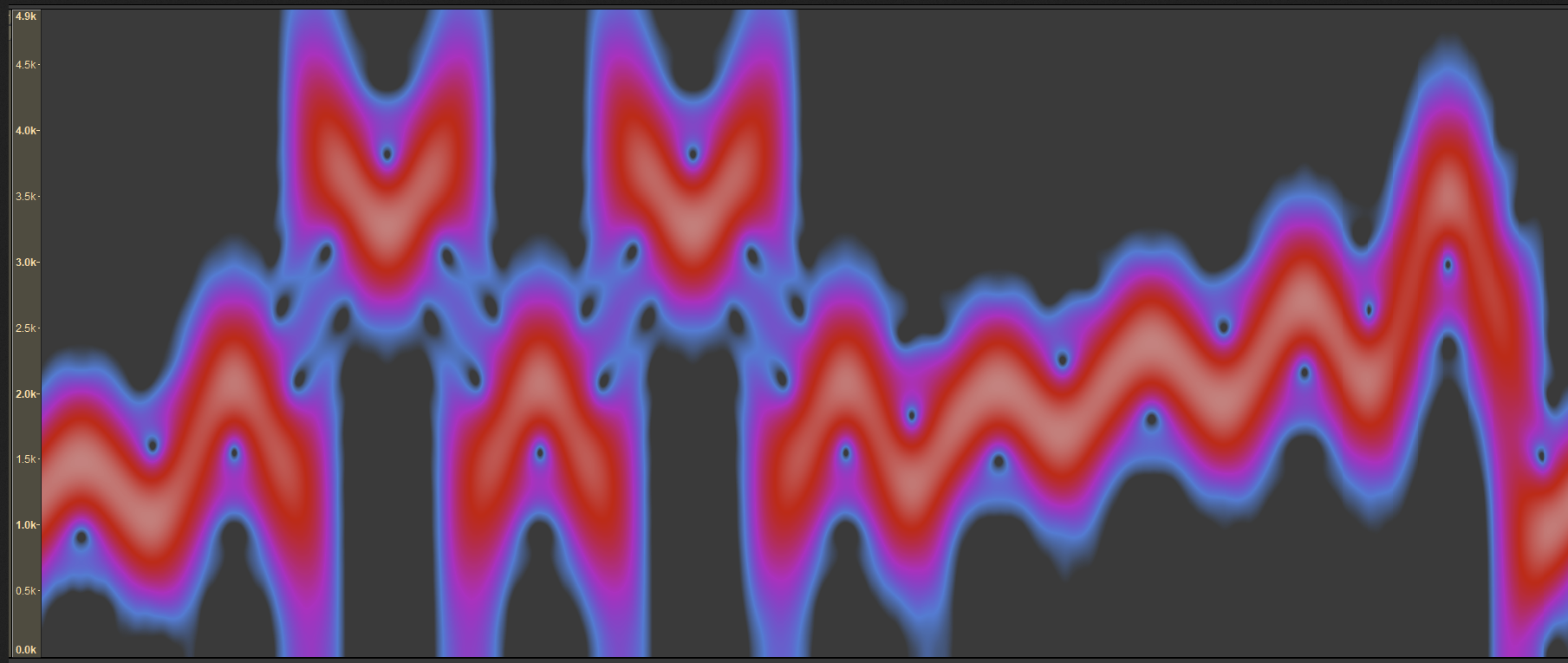
The better SNR of an MFSK signal (2nd) compared to OFDM (1st) is obvious in this spectrograph:

When a short baud period is sent through a narrow tone filter, the waveform is extremely smeared in time, making detection difficult:

Non-orthogonal, closely spaced, short FSK tones can be precisely detected in an FFT using a phase-reversal method. This subtracts the 50% phase flipped (DSB) tone spectrum from the normal tone spectrum to show the difference:

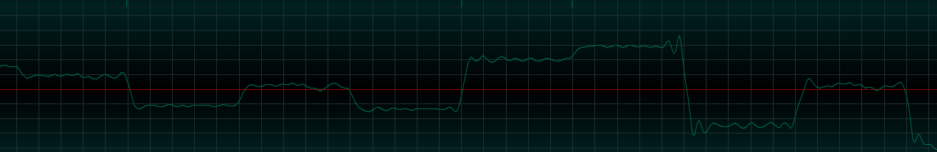
Code Shift Keying is a way of sending data symbols using PN codes. In this example, a PN modulated sinewave is decoded (zero-beat) first using an incorrect PN code (left), then with a matching PN code (right):
Sinewaves can also be chirped using other (lower-frequency) sinewaves. This creates audio-frequency FM. In these graphs, various sinewave chirp patterns are overlayed to check how similar their patterns are.
Ideally, the data symbol chirp patterns should have different shapes, so they still don't overlap when shifted in time - as this can happen due to propagation.
Y axis = Frequency, X axis = Time (baud):


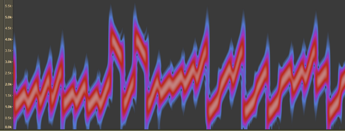
Test1: 257FSK chirped sinewave symbols. Y axis = Frequency, X axis = Time:
Test2: It became apparent that a linear chirp could sometimes result in the chirped signal having a frequency that did not change between bauds. Since this could potentially make decoding more difficult, a time-symmetric chirp was designed. A time-symmetric chirp has the same start and end frequencies.
This type of chirp has become the prime choice, due to the fact that it is easy to recover the clock frequency from the chirp. It is also easy to identify up/down chirps and thus to flip the inverted chirp waveform to make it phase-continuous for optimum filtering and best sync recovery. An even better possibility is to use a sinewave shape for the chirp instead of symmetric ramps.
257FSK time-symmetric chirped sinewave symbols. Y axis = Frequency, X axis = Time: