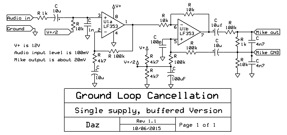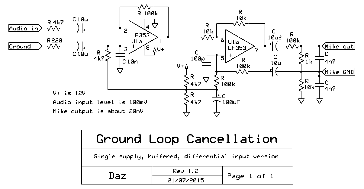
This circuit avoids the need for a coupling transformer when feeding audio from an external source into a transceiver or speech processor mike input. The circuit power supply must share a common negative ground connection with the processor or transceiver.
The input and output are both RF filtered using ceramic capacitors. Gain can be changed by scaling the 4k7 resistor on U1a. Do not earth the Mike GND terminal to the chassis or the power supply. It must only connect as shown. It must also connect normally at the transceiver.
If the input resistance needs to be above 1k, the 1n capacitor may need to be reduced to 100p or so to avoid excessive lowpass filtering of the audio input. A JFET OpAmp is recommended to reduce the RF sensitivity of the circuit, but 741 OpAmps have been tested and work fine also.

Since common OpAmps have noise levels that are too high for a mike input, the audio is amplified by U1a then scaled down again to mike level after U1b. This also improves the ground loop cancellation by an additional 30dB or more.
The circuit performs very well with 1% metal film
resistors. No special parts matching or trimming is necessary.
