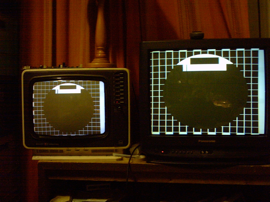
Early stages - B&W only
** NEW PM5544 PROJECT FOR 2012! SCROLL DOWN! **
 |
| The picture is composed of blocks of image
data (kinda like video LEGO!)
Getting the circle to work was a milestone, as it required very close timing that wasn't possible in software using this approach. It was finally accomplished by using the hardware timer to switch foreground/background colours, using a RAMDAC chip programmed with the colours grouped into layers. The RAMDAC was an old TR9C1710 scavenged from a VGA card. It converts the 1-byte colour codes to 6-bit RGB values and does D to A conversion. This saved I/O pins on the microcontroller and
made the software faster.
|
 |
|
Every visible part of the PM5543 was able to be coded easily EXCEPT the frequency gratings. The samplerate using a 16MHz processor was far too low for software DDS. Even hard-coding the gratings at 2 instructions per sample was too slow for the 4.8MHz grating. This equates to 8MHz sampling, resulting in a maximum frequency of 4MHz. Preloading lots of registers (the MEGA-8 has 32) with greyscale data and outputting one sample per clock period may have made it possible, as it would achieve a 16MHz video sample rate (8MHz bandwidth). This would require the software to be rewritten to use RAM storage for most variables. A modern 40MHz+ DSP controller with DMA and
more RAM should have no trouble generating all the PM5543 components, though
the software would need to be completely different.
|
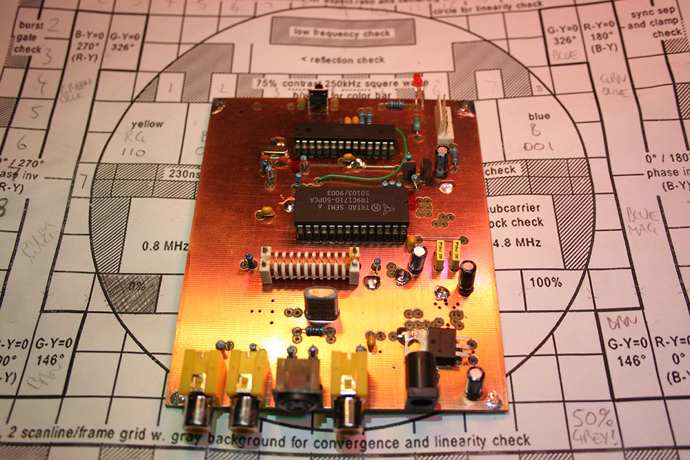 |
| The new homebrew "Philips PM5544 test pattern generator" PCB. It features an Atmel Mega88 microcontroller, a VGA RAMDAC, and an SMD MC13077 PAL colour encoder chip. Each chip cost under $10 AU. The RAMDAC was removed from an old VGA card, so it was free! |
 |
| The colour encoder chip is on order at this stage, so the video output is temporarily wired as monochrome only. The funny looking white thing to the left of the RAMDAC is a video luminance delay line, to compensate for the delay in processing the colour signal. The colour encoder IC is a surface mount chip that is mounted on the PCB underside. |
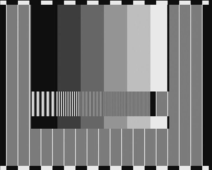 |
Greyscale & Sinewave TestUsing an Atmel Mega88 microcontroller @20MHz, it was possible to generate sinewaves at 20MSPS by preloading a group of 20 registers with greyscale data - to do output in a single clock cycle each. This required efficient usage of the Mega88's 32 working registers. No RAM variables were needed after all! |
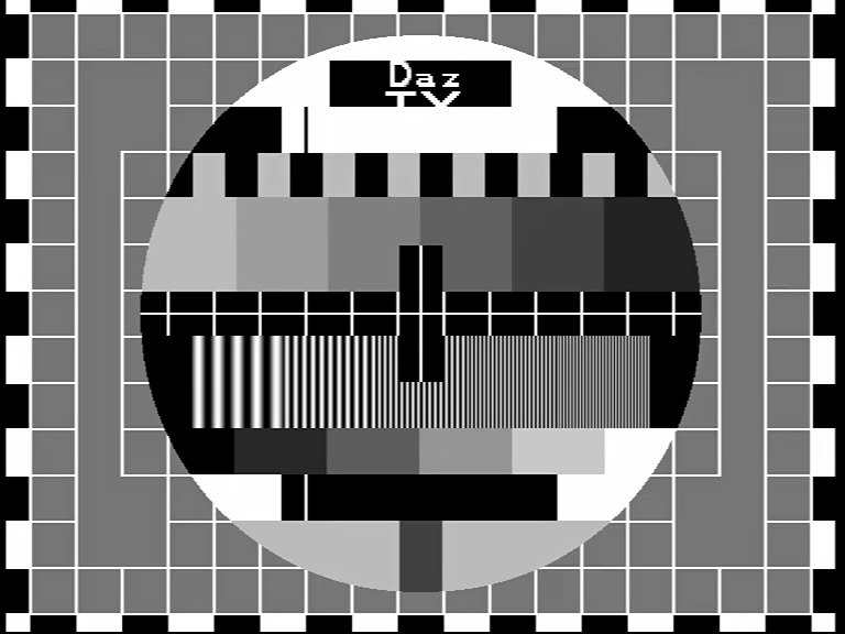 |
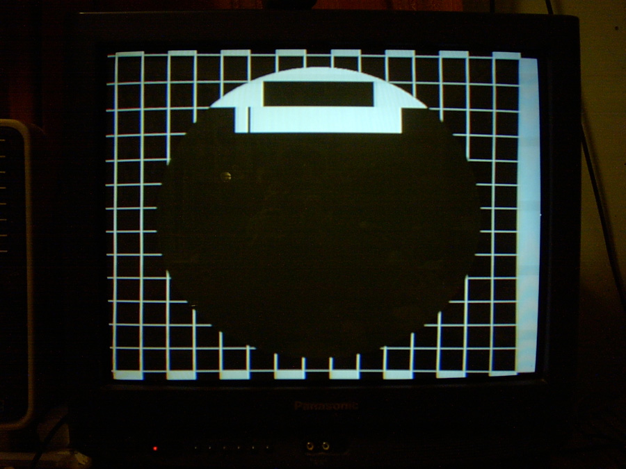
"Philips PM5544 Test Pattern" likenessAfter two solid days of programming, this one is definitely a PASS! All the main PM5544 components are there (except COLOUR - still waiting on the PAL encoder chip to arrive). Circle geometry is now very good. Sinewave timing has been corrected. A small code bug with the sinewave level programming has been fixed. A script to automate the sinewave code generation was written in mIRC, and made the phasing adjustment much easier. Various techniques were
tried to make the software more reliable or easier to program, but the
speed requirements meant that a lot of inline coding was needed.
Basically, the image is coded in LAYERS by having different colour ranges programmed in the RAMDAC. This allows a hardware timer to switch between foreground and background colours to produce the circle overlay. A second version of the software is currently being tested. It stores the pattern colours as a data set, and uses a single routine to read them out and send them to the RAMDAC. It greatly simplifies the program, as only one main routine is used for forming the pattern, instead of one routine for each row (a total of 14), like the first version. The combined code & data size is reduced by about 10%. However, it is more difficult to control program flow with the second version.
The high level of web hits on this page indicate this project is of interest to many people. Here is an overview of
the software flow used:
Each row consists of:
Each large block consists
of:
The delay for drawing the grid lines is a software NOP delay, as the timer interrupt latency is too high for such a short delay. e.g.: Output next colour value
to RAMDAC
|
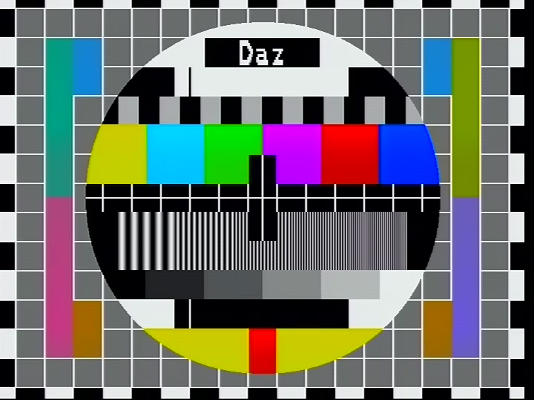 |
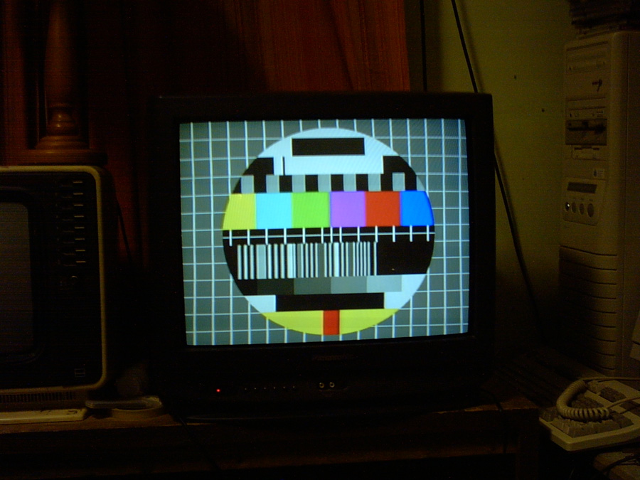
COLOUR!The colour encoder chip arrived today, and was soon installed. The colours aren't exact yet, but they're getting very close. An accurate conversion algorithm is needed to calculate the YUV colour values from the PAL colour phase angles specified in the pattern. The smoothness of the scrolling logo has been improved. Click the picture for
a video!
|
 |
| Nov 11, 2012
An accurate colour conversion algorithm has now been developed. It consists of finding the U and V proportions from the sin() and cos() functions of the colour angle in degrees, and scaling them appropriately to avoid numerical saturation (gamut errors). The pattern colours in software are now exact, with the only remaining errors being in the hardware YUV scaling, which still needs some trimming. Those bracket colours (specified in degrees) were a bit of a mystery, but now it's clear they are mostly made of colours that have U or V values set to their maximum possible excursions. A new chroma bandpass filter has been fitted, and seems to do a good job. It has increased the colour bleed though, due to reducing the chroma bandwidth. It may also have a bit too much delay for the luma delay line. One residual problem is edge "beats" due to the colour subcarrier phase and the pixel clock phase being derived from independent sources. This means the phase/frequency relationship randomly drifts, causing the colour edges to quiver. The solution to this would be to phase-lock the two oscillators, either by a PLL or by deriving both clocks from the same source via frequency multiplication or division. Click the picture for a video.
|
 |
| Nov 13, 2012
Some new filters have removed the video beats occurring due to aliasing between the digital video pixel clock harmonics and the 4.43MHz chroma modulation. The U and V channels have had simple 2nd order elliptic lowpass filters fitted with a notch near 8MHz. This removed the quivering on the colour bar edges. The chroma bandpass filter has been changed to a discrete component version with less delay and greater bandwidth. This improves the Y/C alignment and reduces colour bleeding. No filtering has been added to the luma channel yet, but this only affects composite output, since the Y/C channels are separate on s-video. The phase inversion test signals have been added to the pattern on columns 1 and 17. They are designed to test whether a PAL decoder is able to correctly average out chroma phase errors. Click the picture for
a video.
|
 |
 |
| Nov 14, 2012
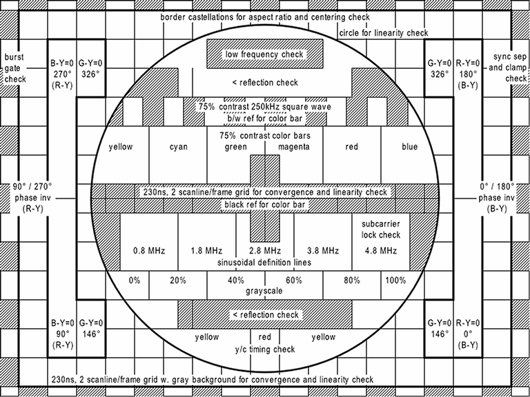
From Wikipedia (public domain images) Here is a reference "Philips PM5544 test pattern" and a reference chart, showing the various components of the pattern. The following differences from the AVR pattern generator are noted:
Some specs from the AVR design (after recent efficiency improvements):
|
 |
A DSP approach
Advantages of this approach include:
The next step will be to try to output some test signals read from a memory buffer, to check signal timing and quality. Using an 8-bit DAC should enable TRUE COLOUR output (256 levels per channel) but only in composite mode. In s-video mode only 4 bits would be available (16 levels) with an 8-bit port - not very practical. The AVR board above uses a timed approach to video generation. It outputs a YUV colour value then waits for the next one. This means the CPU spends a lot of it's time doing nothing, enabling it to do other background functions. A DSP approach is more work, because the CPU has to output every pixel individually. Although where lines have the same data, it can do nothing and just let the DMA read out the same line again! Also, where a line is different the CPU can just update the changed parts and leave the rest of the line alone. These shortcuts might reduce the CPU workload enough to make test pattern generation practical. The dsPIC33FJ64GP802 flash memory (64k) and RAM (16k) are both large enough that the entire image might be able to be coded in RLE (Run Length compression) and stored on-chip. This would reduce the need for on-the-fly computations. It would also enable any kind of pattern to be produced.
|
 |
DSP Video TestAn early version of the software is generating composite sync with a black and white checkerboard pattern. Testing has shown the dsPIC33FJ64GP802 parallel port to be too slow for 4x chroma sampling, but well suited for 3x chroma sampling (13.3MHz). A single chip version of the pattern generator isn't possible, because an 8-bit latch is required for stable output, as the PMP data output is always multiplexed (even with no multiplexed functions selected). However, the extra chip required (74HC574) is cheap, and readily available.
|
 |
 |
DSP Colour Bars and RampThe breadboard version of the DSP pattern generator is now functional, producing colour bars and a ramp. Problems:
The chroma phasing has a problem, in that the picture line count has to be EVEN or the colour fails to work. This is due to a timing issue. Since the sampling is chroma locked, the total number of chroma samples has to be correct for both the phase and frequency to be correct. Solid colour areas have good quality. Colour edges are very sharp - with perfect Y/C alignment, but have some fixed patterning - either due to the line & chroma frequencies being locked together, or the interaction of the sample data as it crosses over from one sample group to the next. Either the sync position or the chroma phase needs to continuously rotate to offset the frequencies and make the patterning move. DSP filtering may be needed to process the sample values as they change from one block to the next. Processing is difficult, as there are 3 (byte) samples in each group (24 bits), yet the dsPIC chip processes data in 16 bit format (2 samples at a time). The R-2R DAC is showing some glitches in the ramp waveform. This is probably due to the imprecise resistor ratio (1k & 2k2), output impedance effects of the CMOS gate, or poor grounding due to the circuit being built on a plugin breadboard. Also there is currently no anti-alias lowpass filter on the video output, apart from one 33pF capacitor.
|
ImprovementsNew experiments using 16 bit DMA and PMP transfer modes have shown that it is possible to operate the DMA driven data port at 4 times the chroma frequency (17.734475 MHz). This is very advantageous, as it makes the chroma and luma timing work together. The 4x chroma sample rate is a very close multiple of line frequency (1135.0064 times). This results in the frequencies and phases being correct automatically, with a tiny error of only 0.64% (100Hz at 15.625kHz). This may still be significant for critical applications. It also means 4 byte groups represent each colour sample, which fits in better with the 16 bit buffer transfers than the 3 byte groups when operating at 3x chroma frequency. In 16 bit mode the PMP needs double latching to make the DAC work correctly. This means using a minimum of 2 ICs to build the video DAC instead of 1. It also requires faster data latches than currently used. Using a proper video DAC, one high speed latch and a fast flip-flop to provide a pixel clock from the CPU clock should work. Unfortunately the readily available video DAC has the data pin ordering in reverse to the dsPIC PMP port. One way to correct this is to mount the DAC flipped upside-down, after reforming the leads. Another way is to use an SMD version of the dsPIC mounted in a SMD adaptor board. This also enables the SMD chip to be unplugged. Using 4x chroma sampling means the CPU will be running 2x this speed (35.46895 MHz), unless another workable timing ratio can be found **. This gives the CPU only a 2:1 raw speed advantage over the DMA, though the 16 bit buffer transfers provide another 2x speedup. This hopefully means that the CPU has a 4x faster ability to write to the buffer than the DMA reads it. The dsPIC hardware repeat and do loops also help to speed the process of writing video to the buffer. **The dsPIC33E could run at 70.9379 MHz (slightly overclocked), and possibly other intermediate speeds, using various PMP wait states. The structure of the new pattern generator software will be a little different, because the DMA buffer is too small to store 2 lines of video at 17.73 MHz, unless the buffer is only used for about 57.7 uS of the 64 uS line. This is one reason why the CPU must run at a precise multiple of the DMA rate, so a hardware timer can generate the sync pulses with exact timing, then return to DMA mode for the visible portion of the line. Using this technique allows alternate lines to be saved in each 1k buffer. This works well with the PAL phasing, and allows video lines that don't change to be read out a second time with no CPU effort. The dsPIC33E with a 4k DMA buffer would avoid this 1k buffer limitation, and double the CPU speed at the same time.
|
Better Hardware Alternatives?dsPIC33E series
Philips SAA7120
ST Micro STi5518
The benefits:
The problems:
|