To prevent power loss and power glitches from causing computer downtime, a UPS system is commonly used. Most systems available use Modified Squarewave inverters to provide AC output in the event of a mains power loss. This can cause some issues, such as buzzing (both audible and electrical - i.e.: in sound and video equipment nearby), and rectifier and filter overheating, due to the steep wavefronts on the squarewave inverter output. Some more expensive systems generate a real sinewave output to get around this, but it adds expense and reduces efficiency slightly. A DC system has none of these disadvantages, and has some advantages:
Most computer equipment
is quite happy to operate from high voltage DC instead of AC. The reason
for this is the prevalence of switchmode power supplies (SMPS). Switchmode
power supplies work by first rectifying the AC into DC, then converting
it to high frequency AC pulses for transformation to a lower voltage. The
high frequency is then rectified again and filtered for the output. This
enables the supplies to use smaller and lighter transformers with far less
copper wire, reducing losses. Some of the newest PC power supplies can
exceed 80% efficiency, which reduces power demands.
Modern equipment using SMPS are happy to operate from high voltage DC power:
Equipment that cannot
operate from a high voltage DC supply includes:
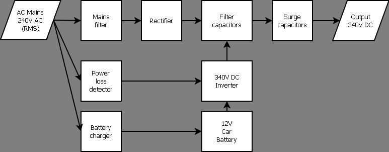
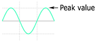
340 volts is the peak voltage of the 240 volt AC
mains (240 x 1.414), so the DC output is at this voltage
The AC loss detector is a simple circuit based on a CMOS inverter IC. It accepts 240 Volts AC, rectifies it, opto-isolates it, and squares the waveform to generate a series of pulses at double mains frequency. The pulses are typically > 5 mS long, and occur every 10 mS (twice per AC cycle). The pulse output is then processed by a 7 mS pulse extender (monostable) to stretch across the gap between pulses. A second pulse extender then smoothes the result to prevent chattering during marginal power conditions. As soon as the AC fails, or drops below the limit, the first pulse extender times out, thus detecting AC power loss within 7 mS. Placing R1 at the AC Active input limits both current and voltage. This allows low voltage diodes to be used, and also linearizes the LED transfer curve in the optocoupler.
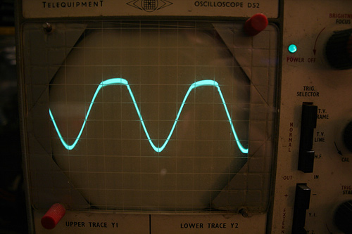
Waveform at optocoupler pin 4, 2mS per division
- showing rectified mains waveform
The DC voltage used is 340 Volts, as this is the peak value of the 240 Volt AC mains waveform.
The units were modified for DC output, and provide
acceptable performance - although the voltage sag is quite severe (drops
well under 300 volts DC at full load)
The end result of all this is a reliable, robust, quiet, uninterruptible power source.
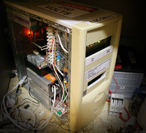
The UPS in operation... Inside the casing a couple
of neon lamps glow to give warning that the various components are live.