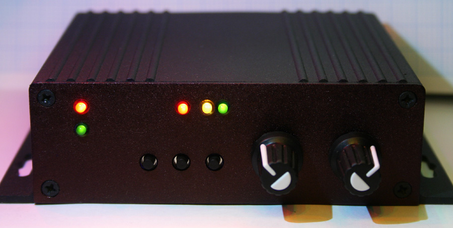
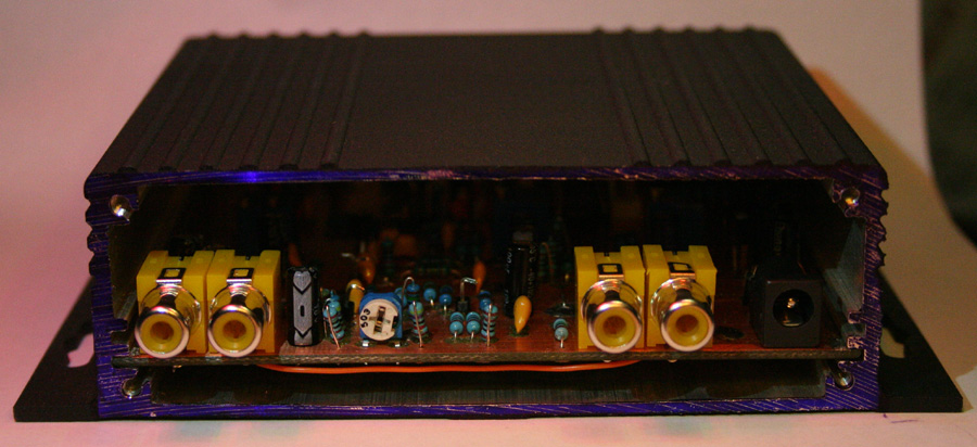
| Concept | Method |
| Do the minimal processing required on a VHS playback analog video signal to improve the performance of a PC video capture device. This should ensure optimal quality, and the best value for money. | Strip the sync pulses from the video and process them before re-insertion. Use the original signal timing except where it causes a problem. Enforce vertical sync to ensure stable captures with no dropped frames. Provide options for fixing various problems such as: dropout noise, loss of sync, timebase jitter and flagging. Operate in S-Video and process luminance (Y) signal only. Use a cheap but fast microcontroller to do the processing logic. Use hardware circuits where timing is critical to avoid adding jitter. |
| Details |
|
| Working functions |
|
| Problems |
|
| Features to add |
|
| Additional ideas - VCR modification |
| Due to the difficulties faced with video timing
problems from non-standard tapes, an additional approach to signal improvement
is being investigated - Fitting a small PCB to the VCR that modifies it's
headswitch timing.
Typical VCRs use a method of timing the headswitching point that relies on a phasing signal from the video head drum. Since PAL video has 625 lines per revolution of the video heads, this equates to a tiny 0.576 degrees of head rotation per video line. Since this is a tiny angle, timing errors are likely. Therefore, the switching point is bound to be unstable unless it can be locked to the video sync as a reference. A microcontroller on a small PCB could be added to the VCR circuitry to fix this problem automatically. An ATtiny2313 microcontroller, running at 20MHz
can process both the headswitching signal, and the video sync. The device
then outputs a replacement headswitching signal to the VCR circuitry. This
replacement phasing signal is timed to put the headswitching consistently
on the end of the last line in the video fields. This means the vertical
sync area is intact, and undistorted by headswitching. It also means the
headswitching occurs below the visible picture area, thus improving video
quality and removing the need for cropping.
|


The approach of replacing the vertical sync is producing encouraging results - even without replacing timing glitches occurring later in the vertical interval. The reason for this is uncertain at this time, but it is probably due to the timing relationships of the replaced sync and the horizontal sync pulses at the headswitching point. This point normally occurs near the end of the visible video field, but due to various reasons it can occur later - in the vertical interval. This is actually a good thing if you are trying to make the headswitching glitch non-visible, but it can make the sync unstable.
It was surprising just how stable the video output of a VCR is. The video line period was always very close to 64uS. Hardly any timing leeway was required in the software. It appears the main timing glitch comes from the headswitching, which can displace the field timing - making one field arrive early, and the other one late. This means those lines are long on one field, and short on the other! A function that automatically adjusts the vertical interval line lengths for minimal jitter still needs to be written.
In the example tape below,
the headswitch was occurring on line 9 and 322, the offsets making line
9 longer, and line 322 shorter than normal.
Weak/noisy Broadcast TV -
HSYNC cleaning (mix of original squared HSYNC and software sync)
In hardware sync mode, the
squared sync input is the dominant signal. The software latches the level
after the transitions to prevent glitches.
Weak/noisy Broadcast TV -
VSYNC enforcement (total software sync replacement)
The half-line offset is
plainly visible. The software correctly identifies and syncs to field 1
and field 2 using pattern matching.
However, if the sync is
corrupted, this process can fail. More work is needed.
| FIELD1 | FIELD2 |
 |
 |
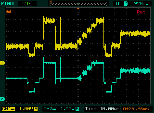
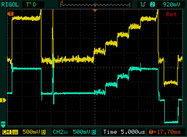
Broadcast TV - Staircase
Waveform - With stabilizer deliberately set to severely clip black and
white levels for testing
The clipper response time
is about 60 to 100 nS depending on level

Not perfect, but much better!
With VCR stabilizer OFF, external stabilizer ON, with completely new VSYNC
pulses generated by microcontroller.
A tiny bend is visible at
the top of the picture. Stability is good.
No special timing ramping
was used, and the headswitching glitch was not removed (on lines 9 and
322).
VSYNC line length was manually
trimmed for best result.
This needs to be made into
an automatic function, as the timing varies as the tape progresses.

Here is a progress update.
A prototype circuit for the video stabilizer has been built, and firmware development is underway. Some additional hardware changes may still be needed.
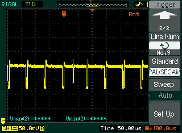
After doing some tests with a tape containing very bad flagging, I have a new idea about a way to repair it. On the example tape, there was a large head switching glitch on line 9 - making it over 80 microseconds long instead of the usual 64uS for PAL. Since this is happening in the vertical interval (where there is no visible video information - only signal timing info) it should be possible to "remap" the timing of the lines in this area to "smooth over" the abrupt change during the headswitch.
The Colossus capture card video decoder (ADV7441A) is rated for a +-5% HSYNC frequency variation, but this bad tape was actually about 30%!! No wonder it had trouble. By remapping the timing in the vertical interval, it should be possible to smooth this error over 25 lines and reduce the peak error to as little as 0.8uS (1.25%). Perhaps an even better way would be to ramp the timing changes up and down to avoid any discontinuity at the end points.
It's challenging though, as coping with variable input and output timing is quite a juggling act...
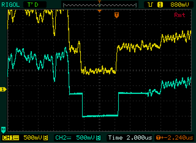
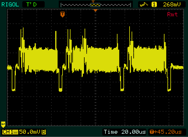
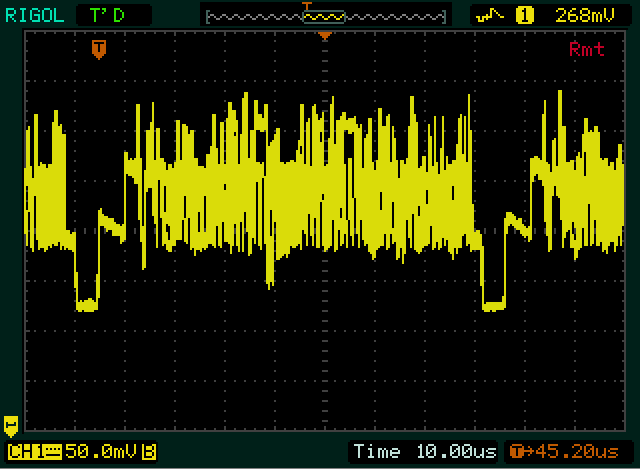
Spot the difference! The
attached images show the timing glitch on the test tape mentioned.
(Actual scaling is 500mV/div
as the probe was inadvertently set to x10)
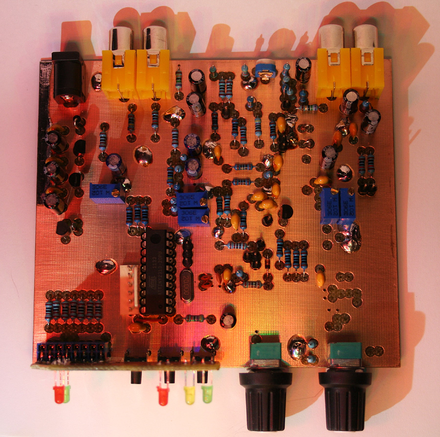
The PCB. Most of the ICs
are SMD and mounted on the underside.
Known Problems:


Front panel - Draft version
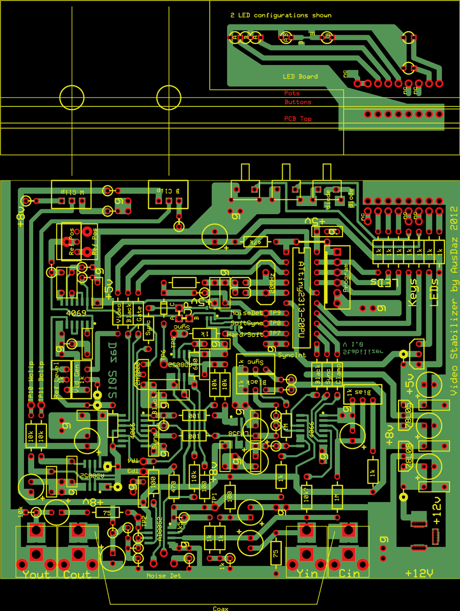
Final PCB Layout